Use this information to install a microprocessor and heat sink in the blade server.
The following notes describe the type of microprocessor that the server supports and other information that you must consider when you install a microprocessor:
- Microprocessors are to be installed only by trained technicians.
Important: Always use the microprocessor installation tool to install a microprocessor. Failing to use the microprocessor installation tool may damage the microprocessor sockets on the system board. Any damage to the microprocessor sockets may require replacing the system board.
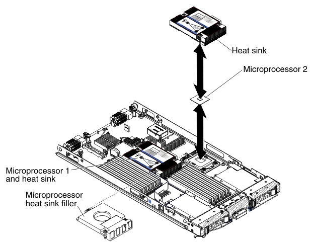
- Each microprocessor socket must always contain either a socket cover and heat-sink filler or a microprocessor and heat sink. If the blade server has only one microprocessor, it must be installed in microprocessor socket 1.
- If you are installing a second microprocessor, make sure that the microprocessors are identical in core speed, QPI, cache size, core quantity, and power segment. The system might hang, if the installed microprocessors are mismatched.
- Before you install a new microprocessor, download and install the most current level of UEFI code (see Updating firmware and device drivers).
- When you install a second microprocessor, you might have to install additional memory, or redistribute memory across the DIMM connectors (see Installing a memory module).
- The microprocessor installation tool might become worn after several uses. Make sure that the tool can hold the microprocessor securely if you are reusing an existing microprocessor installation tool. Do not return the tool with other parts that you are returning.
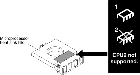
- The server supports only one microprocessor when the certain microprocessor
is installed in microprocessor socket 1. For example, microprocessor
Intel Pentium 1403, Intel Pentium 1407, or Intel Xeon E5-1410. The
following illustration attached on the microprocessor socket 2 filler
shows that microprocessor socket 2 is not supported.
The following illustration shows how to install a microprocessor and heat sink in the blade server.
Attention:
- Do not use any tools or sharp objects to lift the release levers on the microprocessor socket. Doing so might result in permanent damage to the system board.
- Do not touch the contacts in the microprocessor socket. Touching these contacts might result in permanent damage to the system board.
To install a microprocessor and heat sink, complete the following steps:
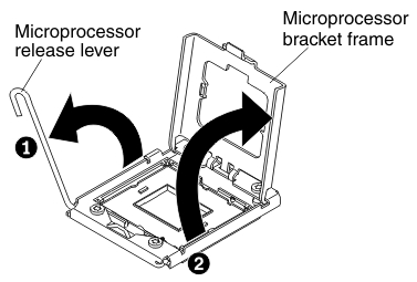
- Open the microprocessor socket release lever and retainer:
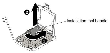
- Install the microprocessor in the microprocessor socket:
- Align the installation tool with the microprocessor
socket. The installation tool rests flush on the socket only if properly
aligned.
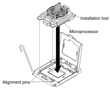
- Twist the handle on the microprocessor tool counterclockwise
to insert the microprocessor into the socket. The microprocessor is
keyed to ensure that the microprocessor is installed correctly. The
microprocessor rests flush on the socket only if properly installed.
 Attention:
- Do not press the microprocessor into the socket.
- Do not touch exposed pins of the microprocessor socket.
- Make sure that the microprocessor is oriented and aligned correctly in the socket before you try to close the microprocessor retainer.
- Do not touch the thermal grease on the bottom of the heat sink or on top of the microprocessor. Touching the thermal grease will contaminate it.
- Align the installation tool with the microprocessor
socket. The installation tool rests flush on the socket only if properly
aligned.
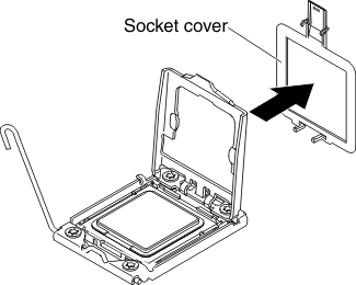
- Remove the socket cover, if one is present. Keep the socket
cover in a safe place for potential future use.
- Close the microprocessor socket release lever and retainer:
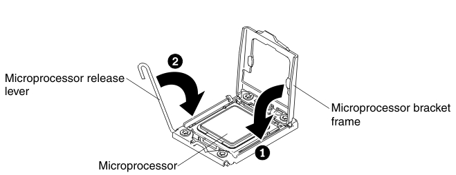
- Close the microprocessor retainer on the microprocessor socket.
- Close the release lever on the microprocessor socket.